The computer motherboard

The computer motherboard
The computer motherboard is the second most important hardware component of a desktop computer system build.
The computer motherboard is a component that must withstand extreme temperatures and withstand continuous shutdown and restart. To ensure that the motherboards are able to meet the demanding tolerances, they are developed and manufactured with care and attention to detail.
Each component and peripheral device associated with a specific computer depends on the motherboard. Whether connected to your computer by any means, through a port, expansion slot, universal serial bus (USB) or wireless via Bluetooth or infrared, it all depends on the motherboard support. There is much more to these complicated circuits than it seems. A modern motherboard is a complex piece of circuitry that deserves further investigation.

How is a computer motherboard made?
Designing and manufacturing the computer motherboard is a long and complicated process. The development of a new motherboard involves working closely with the chipset manufacturer of the central processing unit (CPU). The new state-of-the-art motherboards are designed to incorporate the latest advances in technology. Once the chipset manufacturer and motherboard manufacturer are satisfied with the design, it will go into production.
The computer motherboard manufacturer will design several similar motherboards based on the same chipset. The product will have different specifications, dictated by the price range on the market. In some cases, the collaboration of chipset manufacturers will require specific elements or components to be added to the products. Like all industries, the main factor in terms of specifications and components used is cost. Low-end or cheaper motherboards rarely contain the latest technology that can be found in more expensive high-end motherboards.
The actual process of making motherboards is much more complicated than many people would realize. It would be easy to assume that these complex hardware components are built on robotic machine production lines. In fact, the motherboard manufacturing process is only partially automated and relies heavily on human labor.
The first part of the process is to add surface mount technology to a blank or blank printed circuit board (PCB). Bonding is done automatically by heating the plate to melt and restore the pre-applied bonding. Large components are placed in place by human labor before the motherboards are inspected and tested. The circuit board is subjected to a series of intensive tests, which usually include a combustion test. This is a specific procedure that recreates the stress extremes that the device will encounter throughout its life. Once the motherboard has passed quality control, it can be packaged ready for distribution and retail. The entire manufacturing process takes about 15 minutes from start to finish.
Central processing unit and chipset support.
The chipset of the central processing unit is important because it is an integrated technology. The chipset is optimized to work with a specific processor. The chipset cannot be removed or upgraded. The on-board chipset dictates which CPU units are compatible with the motherboard.
Graphics chipset support.
Some low-end motherboards have built-in graphics adapters on board. In more advanced motherboards, graphics cards are added using an expansion slot on the motherboard. The current technology is PCI Express (PCIE), which has replaced PCI and AGP, respectively. A major step forward in supporting graphics chipsets for the motherboard has been the inclusion of both Nvidia SLI and ATI Crossfire on the same motherboard. This means that the end user has the option to choose to install an Nvidia graphics card or an ATI Radeon graphics card.
Data bus or BUS speed.
The term bus is used to describe the architecture of data transfer in computer systems and electrical circuit boards. It derives from the word bars which is a strip (or hollow tube) of copper or aluminum used to conduct electricity most frequently in power stations. This borrowed and shortened term is now used exclusively to describe the rate of data transfer in a computer system. The bus speed is the calculated data transfer rate and is measured in megahertz.
The Northbridge Chipset.
Most motherboard manufacturers incorporate Northbridge and Southbridge chipsets into their products. These chipsets are designed to prevent blocking (slowing down) computer performance during heavy tasks. The appearance varies from board to board, but in basic Northbridge terms (also known as memory controller). In most cases, Northbridge controls communication between the central processing unit (CPU), the graphics processing unit (GPU), and memory. The Northbridge chipset or controller is a very significant component of the motherboard.
The Southbridge Chipset.
The Southbridge chipset is responsible for communication between component lenses on the motherboard. In a typical system, the Southbridge controller communicates with the PCI bus, real-time clock, power management and a few other devices.
The term “motherboard” or “mainboard” refers to the second most important component found inside a personal computer or PC. It is a large circuit board mounted on one side or the bottom of the computer case, depending on the type of computer. Even laptops contain a motherboard, but they are designed specifically for the laptop in which they are mounted. There are several types of motherboards and they are classified by the type of housing they fall into, also known as the form factor. ATX and mATX or micro ATX are the two most common types installed in most modern computers.
The role of the motherboard is to allow everyone to communicate with each other. The circuit board contains a series of ports or connectors that allow the various internal components of the computer to communicate with the processor, memory, etc. All these connectors have a role and allow different components and devices to be mounted or installed internally or externally.
In the rest of this article we will explain the function of each of these ports or connectors and the devices that can be connected to them.

CPU socket or processor socket.
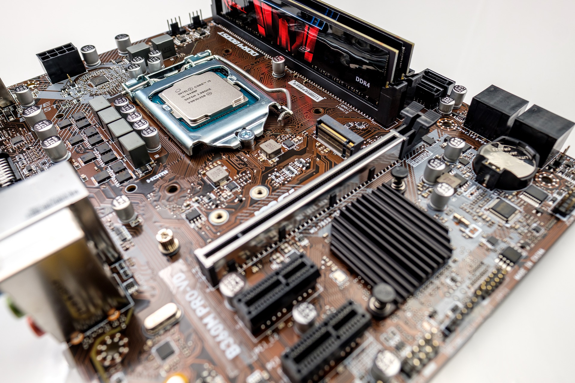
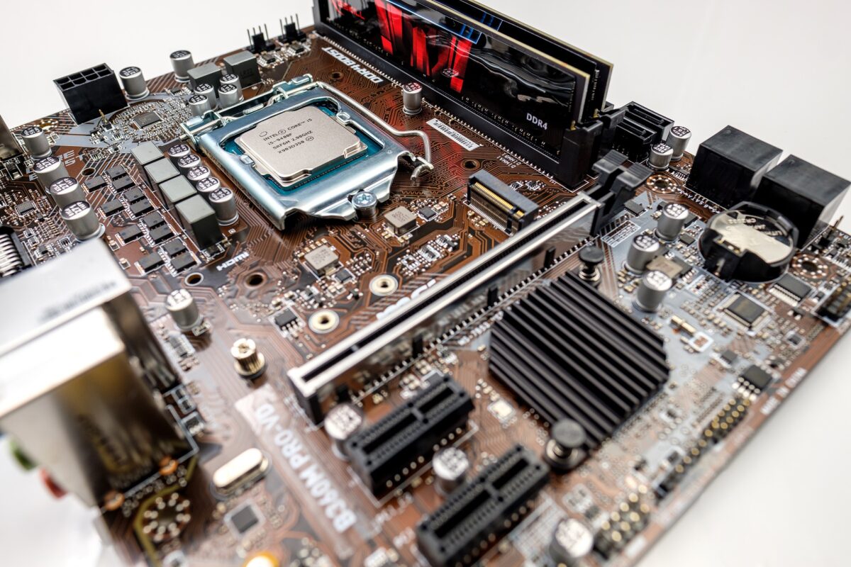
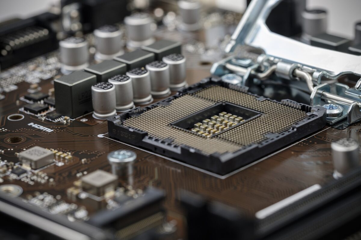
The CPU socket is quite explanatory because it has a CPU. There are different types of processor available and each is designed to fit a specific type of CPU socket. The socket is designed so that the processor can be mounted in one direction only. This is usually caused by a series of notches cut from the edges of the processor. These notches will fit the processor socket for the correct installation of the processor. The CPU motherboard socket usually contains a mechanism or locking device to securely lock the processor securely in the socket.
PSU connector.
The PSU connector is the largest plug connector on the computer motherboard. It is ussualy mounted on the long edge of any computer motherboard. On the other side of the mainboard, you’ll find all the conections with the periferics, usb ports, audio and graphic plugs. The modern PSU plugs have 24 pins. The PSU (Power Supply Unit) has another cable with 4 to 8 pins that will be used to power up the CPU. For that in the upper left corner of the computer mainboard, you’ll find the 12V conectors for the CPU power.
Memory slots
RAM slots hold the computer’s RAM in place. Motherboards may have different amounts of memory slots mounted. Most home computers have two, three, or four slots. As in the processor socket, memory slots are designed to contain specific types of memory. Slots have a number of high points designed to match the correct type of memory mode, it also helps determine the orientation of the memory when installed. A small locking device can be found at each end of the slot. These latches are opened before the memory module is installed and lock it in place when the module is inserted into the slot.
SATA connectors
These connectors allow you to install devices such as hard disks and CD / DVD drives in your computer. The amount of these connectors varies depending on the motherboard. The connector can be recognized by the small L-shaped plug that prevents improper mounting of SATA cables.
IDE / PATA connectors.
These are the oldest types of connections for disk and CD / DVD drives. Older motherboards can have two of these connectors, one primary and one secondary. An IDE cable would be used to connect up to two devices to each connector. The connector has two rows of pins and a notch cut on one side that allows for easy mounting of the cables, making sure they are mounted correctly. Modern motherboards can have a single IDE connector mounted to allow the installation of an older hard disk or CD / DVD drive.
Graphic slots AGP, PCI-Express.
This is a brown slot used to fit AGP graphics cards, on some old motherboards. It would have a small latch on one end to hold the graphics card in place. On modern motherboards, AGP slots have been permanently replaced by PCI Express slots. Like oders, they can be blue and more recently black.
PCI, PCI-E, mini PCI-Express expansion card slots.
They are usually white, and the number may vary depending on the motherboard. The old PCI has now been replaced by the PCI-E or PCI Express standard. They allow you to install expansion cards such as sound, network or multimedia cards, allowing you to easily extend the functionality of your computers. Mounting a card simply involves pushing the expansion card into the slot when the computer is turned off.
The computer motherboard connectors required for external modules.
The motherboard contains a number of small connectors in different locations around the board. They usually consist of a high number of pins. These header connectors have a variety of uses. Some allow you to connect USB ports located on the case, others are for connecting audio connections on the front panel, such as headphone jacks and a microphone on the computer case. Connecting to these headers can be difficult and it is usually necessary to consult a motherboard manual.
External ports.
There are a number of ports on the back edge of the motherboard that are visible on the back of the computer. These may vary depending on the age of the board. Common ports are PS2, which are colored purple to connect a keyboard, green to connect a mouse. There may also be a parallel red printer port, although these are rarely found on modern boards. Another less common port on modern boards are turquoise serial connectors that are used to connect a variety of devices, such as old moderns, barcode scanners, and so on. but this is not always present. There are also USB and audio connection ports located on the back of the board, allowing external USB devices and speaker systems or microphones to be connected to the computer.
As we can see above, the motherboard is the centerpiece when it comes to connecting all the components of the computer inside and outside the computer. So how does the motherboard control all these devices and allow them to communicate successfully?
There are sometimes one or two microchips on the motherboard that control the functions of the motherboard. They are sometimes known as chipsets, but the correct names are the “Northbridge” and “Southbridge” chipsets. Each has a specific role for controlling the various communication functions between the various components connected to the motherboard.
